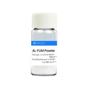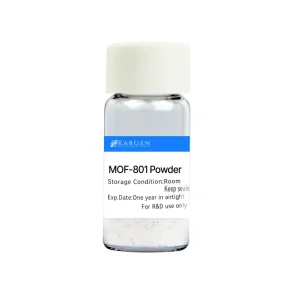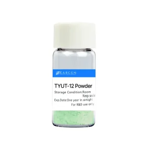
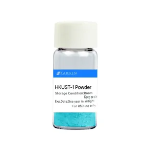
High-Purity Battery-Grade MOF Materials (Shelf 1)
Engineered Metal-Organic Frameworks optimized for selective ion-transport channels, separator coatings, and electrolyte additives.
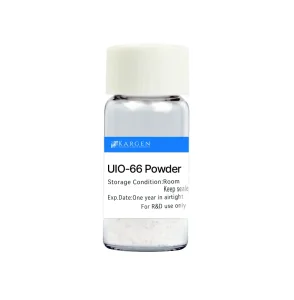
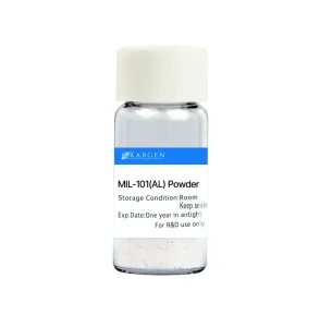
Macro-Industry Landscape: The Paradigm Shift to Li-Metal Anodes
The global energy storage ecosystem is experiencing an unprecedented inflection point. As electric vehicle (EV) OEMs, solid-state battery pioneers, and defense-aerospace contractors push for specific energy densities exceeding 500 Wh/kg, conventional graphite (theoretical capacity of 372 mAh/g) and silicon-composite anodes have approached their physical thermodynamic limits. Metallic lithium, possessing an ultrahigh theoretical specific capacity of 3,860 mAh/g and the lowest negative electrochemical potential (-3.040 V vs. standard hydrogen electrode), represents the holy grail of battery anodes.
However, commercializing metallic lithium anodes has been hindered for decades by severe electrochemical vulnerabilities: uncontrolled lithium dendrite growth, immense volumetric expansion during cycling, fragile solid-electrolyte interphase (SEI) degradation, and low Coulombic Efficiency (CE). Unchecked dendrites penetrate traditional polyolefin separators, causing internal short circuits, rapid capacity fade, and catastrophic thermal runaway events.
The Metal-Organic Framework Solution: Advanced functionalization using customized MOF powders—such as ZIF-8, UiO-66, HKUST-1, and MIL series—introduces uniform, sub-nanometer ionic channels and high mechanical shear modulus interlayers. This homogenizes the electric field, regulates Li-ion solvation sheaths, and physically suppresses dendrite nucleation at scale.
Electrochemical Bottlenecks of Unmodified Lithium Anodes
When lithium ions deposit onto an unfunctionalized lithium metal surface during fast charging, local electric field concentration occurs at micro-protrusions (the "tip effect"). This accelerates ion flux toward localized high-field regions, resulting in mossy, branched dendrite structures. Furthermore, organic liquid electrolytes continuously react with fresh lithium, consuming active lithium and electrolyte solvent while forming a thick, high-impedance, heterogeneous SEI layer.
Nanoscale Electrochemical Mechanisms of Battery-Grade MOFs
How open metal sites, sub-nanometer pore diameters, and tailored organic linkers govern ion flux and interface kinetics.
Li-Ion Transference Number ($t_{Li^+}$) Enhancement
Uncoordinated metal centers (e.g., Cu²⁺ in HKUST-1, Zr⁴⁺ in UiO-66) immobilized within the MOF skeleton selectively anchor electrolyte anions ($PF_6^-$, $TFSI^-$). This unleashes free $Li^+$ movement, increasing the lithium transference number from ~0.35 in conventional liquid electrolytes to 0.75 - 0.91, dramatically minimizing concentration polarization.
Solvation Sheath Desolvation & Homogenization
The periodic sub-nanometer pores (3 Å to 15 Å) of MOFs act as physical sieves. As solvated $[Li(EC/DEC)_4]^+$ complexes pass through MOF windows, bulky solvent molecules are stripped off, lowering the activation energy ($\mathbf{E_a}$) of desolvation and ensuring uniform, 2D planar lithium electrodeposition.
Scavenging Trace Water & HF Species
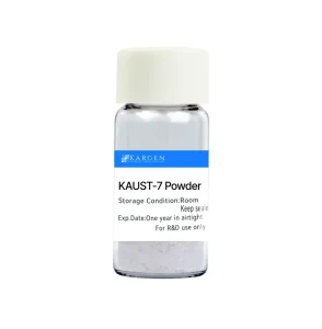
Trace moisture ($H_2O < 50 ppm$) in electrolytes generates hydrofluoric acid ($HF$), accelerating transition-metal dissolution and SEI breakdown. High-stability frameworks like MIL-101(Al) and KAUST-7 rapidly adsorb trace moisture and neutralize acidic byproduct radicals, protecting the anode interface.
Technical Comparison: MOF Frameworks for Battery Applications
| MOF Framework | Pore Window Size (Å) | Thermal Stability (°C) | Primary Electrochemical Function | Integration Method |
|---|---|---|---|---|
| ZIF-8 (Mechanochemical) | 3.4 Å | > 420 °C | Hydrophobic ionic channel, artificial SEI layer construction | Separator slurry coating / Anode interlayers |
| UiO-66 (Zr-based) | 6.0 Å | > 500 °C | High $t_{Li^+}$, anion trapping via lewis acid Zr sites | Solid-State Electrolyte (SSE) additive |
| HKUST-1 (Cu-BTC) | 9.0 Å | > 250 °C | Open metal center activation, rapid ionic diffusion matrix | Composite Gel Polymer Electrolyte (GPE) |
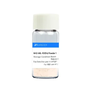
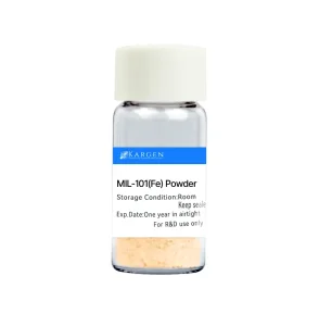
| MIL-101(Fe/Al) | 12.0 - 16.0 Å | > 350 °C | Trace electrolyte acid/moisture scavenger, redox mediator host | Anode top-coat / Porous matrix filler |
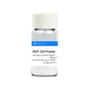
| KAUST-7 / MOF-303 | 3.0 - 4.5 Å | > 300 °C | Ultra-selective mono-valent ion sieving, high pressure resistance | Ultrathin protective membrane layer |
Global Commercialization & Industrial Supply Chain Overview
The global battery industry is rapidly transitioning from lab-scale MOF experimentation to ton-scale industrial adoption. Major gigafactories across Asia, Europe, and North America are integrating advanced functional nanomaterials into their next-generation battery cell pipelines. As a leading manufacturer and exporter in China, our facilities bridge the gap between academic syntheses and commercial cost-parity metrics.
Asia-Pacific (APAC) Manufacturing Dominance
APAC remains the epicenter of battery innovation, controlling over 75% of global cell manufacturing capacity. China-based suppliers lead the scale-up of green mechanochemical synthesis for MOF powders. By replacing expensive organic solvents (like DMF) with continuous solvent-free or aqueous mechanochemical extrusion, batch-to-batch consistency is guaranteed while lowering unit costs by up to 65%.
Western OEM Integration (NA & EU)
Automotive OEMs in North America and Europe are setting aggressive targets for 450 Wh/kg - 500 Wh/kg pouch cells by 2028. Regulatory demands under the EU Battery Regulation mandate high environmental standards, non-toxic linkers, and full lifecycle traceability—criteria seamlessly met by our ISO-certified, REACH-compliant MOF manufacturing operations.
Technology Readiness Level (TRL) Assessment
Battery-grade MOFs are no longer purely theoretical. Separator coatings incorporating ZIF-8 and UiO-66 are currently at TRL 7 (System prototype demonstration in an operational environment), with pilot pouch cell tests demonstrating over 1,500 continuous fast-charge cycles (4C rate) at room temperature with zero capacity drop caused by dendrite short-circuits.
Technology Roadmap & Future Outlook (2025–2035)
Decadal projection of MOF applications in solid-state electrolytes, anode-free architectures, and lithium-sulfur systems.
2025–2027: MOF Separators
Widespread roll-out of ultrathin (1-2 µm) MOF slurry-coated polyolefin separators for high-voltage liquid lithium-ion and semi-solid batteries. Immediate focus on lowering $DCIR$ (Direct Current Internal Resistance) and preventing thermal runaway.
2027–2030: Pure Li Anode Interlayers
Commercial deployment of 3D monolithic MOF host frameworks directly on ultrathin (15-20 µm) lithium foil. Enables 500 Wh/kg energy density for eVTOL aircraft and long-range electric vehicles with 10-minute fast charging capability.
2030–2035: Anode-Free Solid State
Integration of single-ion conducting MOF matrixes into All-Solid-State Batteries (ASSBs) and Anode-Free Cell configurations. Zero excess lithium required; complete physical suppression of dendrites via 100% rigid inorganic-organic MOF crystal networks.
Localized Application Scenarios & Engineering Integration Methods
Translating pure MOF powders into commercial battery performance requires localized engineering protocols aligned with cell assembly equipment (roll-to-roll coaters, slot-die heads, and dry-room assembly lines).
1. Separator Coating via Roll-to-Roll (R2R) Slot-Die
MOF powders (e.g., ZIF-8, UiO-66) are dispersed in aqueous or solvent-based systems (NMP/PVDF or Water/CMC-SBR) with a particle size distribution ($D_{50} < 200 nm$). The slurry is applied onto standard PE/PP separators at a thickness of 1.0–1.5 µm. This micro-porous functional layer exhibits superior electrolyte thermal shrink resistance up to 220°C.
2. Solid Polymer Electrolyte (SPE) Matrix Filler
Incorporating 5–10 wt% of activated UiO-66 or MIL-101 into PEO (polyethylene oxide) matrixes disrupts polymer chain crystallization. This increases room-temperature ionic conductivity from $10^{-6} S/cm$ to $10^{-4} S/cm$, allowing solid-state batteries to operate efficiently at ambient temperatures.
3. Direct Anode Protective Interlayer (In-Situ / Ex-Situ)
Applied via magnetron sputtering, doctor-blade coating, or Langmuir-Blodgett deposition directly onto copper foil or lithium metal surfaces. The porous framework creates an artificial SEI layer that absorbs mechanical stress caused by volumetric changes during plating/stripping.
4. Lithium-Sulfur (Li-S) Polysulfide Trapping
In Li-S architectures, conductive carbon-MOF composites host sulfur cathodes. Open metal centers chemically bind soluble lithium polysulfides ($Li_2S_n, 4 \le n \le 8$), completely suppressing the shuttle effect and preserving high capacity over 1,000 deep cycles.
Global Compliance, Quality Control & Localized Technical Support
As a global OEM/ODM manufacturer and exporter, we enforce rigorous quality management systems to guarantee industrial reliability, batch consistency, and smooth international customs clearance.
Strict Analytical QC
Every single batch undergoes Powder X-Ray Diffraction (PXRD) phase verification, Nitrogen Physisorption BET surface area analysis (>1,500 m²/g), ICP-OES metal ion purity checking, and Karl Fischer titration ($H_2O < 50 ppm$).
International Regulatory Assurance
Full compliance with EU REACH registration, RoHS 2.0 directive, Toxic Substances Control Act (TSCA), and UN 38.3 safe chemical transport regulations. Complete SDS and COA documentation accompanies every shipment.
Global Logistics & ODM Technical Team
Our dedicated engineering department provides 24-hour localized technical consulting, OEM surface modification (silane coupling, hydrophobization), slurry dispersion formulation aid, and fast sample fulfillment (1-5g free evaluation lots).
Frequently Asked Questions (FAQ)
Engineering and procurement insights regarding battery-grade MOFs, sample testing, and industrial integration.
How do MOFs physically suppress lithium dendrites compared to traditional alumina ($Al_2O_3$) separator coatings?
While ceramic alumina coatings provide thermal stability, they possess non-uniform interparticle voids ($>100 nm$) that do not homogenize Li-ion flux. MOF crystals feature ordered, sub-nanometer intrinsic crystalline pores ($3-12 Å$). These nanometer channels act as ion transport guides, forcing uniform lithium nucleation. Additionally, open metal sites in MOFs bind anions, boosting the Li-ion transference number and mitigating concentration polarization, which is the root driver of dendrite growth.
What particle size distribution ($D_{50}$) is supplied for battery separator slurry preparation?
For battery applications, we offer micronized nano-grade MOF powders with a narrow particle size distribution ($D_{50} = 150 nm - 300 nm$). We also supply pre-dispersed liquid slurries (in NMP, Water, or Ethanol) with customized surfactant packages to prevent particle agglomeration during slot-die coating.
Are MOF powders stable against organic carbonate and ether-based battery electrolytes?
Yes. Frameworks such as ZIF-8, UiO-66, and MIL-101(Al) exhibit exceptional chemical stability in standard carbonate solvents (EC, DEC, DMC, EMC) as well as ether solvents (DME, DOL) containing $LiPF_6$, $LiTFSI$, or $LiFSI$ salts across the full operating window of 0V to 4.5V vs. $Li/Li^+$.
Can KARGEN provide custom organic linkers or functionalized MOF variants (OEM/ODM)?
Absolutely. Our R&D center is equipped to synthesize customized derivative frameworks—such as amino-functionalized ($NH_2-UiO-66$), lithiated frameworks ($Li-MOFs$), or fluorinated linkers—tailored specifically to your solid-state electrolyte chemistry or targeted cell voltage profile.
What is the lead time and scale-up capacity for industrial ton-scale orders?
We operate China's first ton-scale MOF manufacturing facility. Standard grades (ZIF-8, HKUST-1, UiO-66, Al-FUM) are available off-the-shelf for rapid sample dispatch (1-3 days). Commercial bulk orders (100 kg to multi-ton lots) are delivered within 2-4 weeks with full batch COA documentation.
How can R&D teams obtain 1–5 gram evaluation samples?
Qualified battery research institutions and industrial cell development teams can request 1-5 gram free evaluation samples. Simply contact our sales engineering team via email with your project parameters and material specification requirements.
Specialty & Gas Separation MOF Products (Shelf 2)
Comprehensive Metal-Organic Framework powders engineered for gas separation, liquid purification, catalytic conversion, and advanced energy storage.